Interface Standards
RS-530 (often written as RS530) is a specification for a differential communications interface that uses a DB-25 connector and differential equivalents of the V.24 (RS-232) signals. The majority of the signals conform to the RS422 standard and for the majority of requirements requiring RS422 signalling the RS530 cable is suitable. Some of the link management controls signals are implemented using V.10 (RS-423) single ended interfaces, and a variant of this standard called RS-530A / EIA-530A also uses V.10 for the DTR signal. Note that the EIA standards have effectively replaced the RS standards and have now been themselves superceded by TIA standards.
Interface Characteristics
RS-530 is a differential communications interface with some single-ended link management signals, typically limited to a maximum throughput of 10Mbps. Communications over distances exceeding 1000m is possible at low bit rates, the actual performance being mostly dependent on cable specification. Separate clock lines are used for receiving and transmitting data.
Interface Applications
EIA530 interfaces are commonly found on communications equipment in some parts of the world where high throughput and/or long distances are required. The interface also offers good noise immunity enabling reliable communications in environments where there are high levels of EMI (electromagnetic interference).
Applications include high-speed connections between satellite modems and host computer systems.
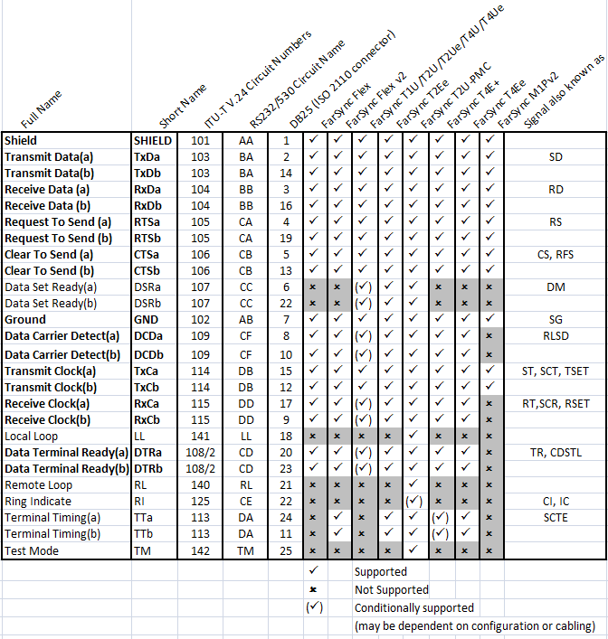
Interface Connector Types and Pinouts
The signals used by the overwhelming majority of applications are marked in bold.
The RS530, EIA530 standard is supported on the FarSync range of communications products