Interface Standards
V.24 is a specification that defines the signal functions, ISO2110 defines the pinout for a DB25. It is used together with V.28 to define a specification for serial asynchronous or synchronous communications.
V.28 is a specification for single-ended communications that defines signal electrical characteristics. It is used together with V.24 to define a serial communications specification used for asynchronous or synchronous communications. V.28 signals are used in V.24 and in part of V.35 interfaces.
RS-232 is essentially equivalent to a combination of V.24 and V.28. Note that the EIA standards have effectively replaced the RS standards and now they have become TIA standards.
X.21bis is a standard that incorporates a subset of V.24 but its use is in decline.
RS232C is often quoted when RS232 is required, it is a revision of the RS232 specification, now superceded by RS232D, RS232E and TIA232F, FarSite generally quote RS232 in our technical details, our RS232 interfaces comply to, at minimum RS232C.
Interface Characteristics
V.24 is a single-ended interface, typically limited to a maximum throughput of 115Kbps. Communications distance is typically limited to 6m, the actual performance being mostly dependent on cable specification. Note that some examples of these interfaces are capable of higher (‘non-standard’) performance due to technological advances that enable interface integrated circuits to support bit rates exceeding 230Kbps. In synchronous mode, both receive and transmit clocks are used to transfer data (both clocks are driven by one end of a connection).
Interface Applications
One of the most common applications of V.24 interfaces is for the ubiquitous COM port and the matching serial ports of the many types of peripheral devices that can be attached to them. These implementations use the asynchronous mode of communications (ASYNC).
V.24 is also used for interfaces operating in synchronous mode, for example to connect a synchronous modem on a leased-line to a synchronous communications adapter installed in a host computer system. Typical protocols used over synchronous V.24 interfaces are HDLC, X.25, SNA and PPP.
Interface Connector Types and Pinouts
DB25
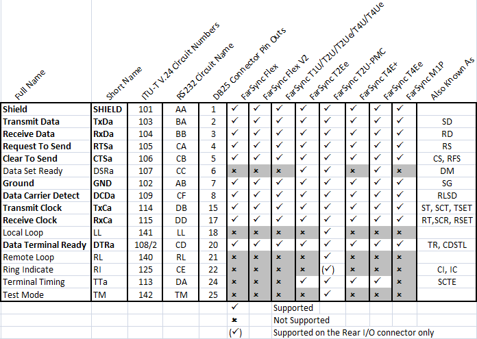
The DB25 connector is used for both synchronous and asynchronous type connections. Many of the signals defined in the standard were little used right from their inception, the signals used by the overwhelming majority of applications are marked in bold, as can be seen from the table below they are very much a subset of the complete standard.
The V.24 / RS-232 standard is supported on the FarSync range of communications products